PRODUCT CATEGORY
CONTACT US
- Tel: 0086-311-89642206
- E-mail: sales@hbmetals.com
- E-mail: info@hbmetals.com
Cast Iron Wafer Type Butterfly Valve Technical Specification
1. Introduction to cast iron wafer type butterfly valve.
The butterfly valves is a quarter-turn rotary valve which has a round disc as closure member that is rotated through 90 degrees to open or close the flow passage. As an inexpensive metal, cast iron(grey iron or ductile iron) is mostly used in concentric butterfly valves for simple on-off applications. The wafer type refers to its valve body style and sometimes it is also called flangeless type.The wafer type body is a flat body that has a minimal face-to-face length, which is usually equals to twice the required wall thickness plus the width of the packing box. Hebei Metals Industrial Limited generally supplies and stocks wafer type cast iron butterfly valves from 2" to 12". Sizes larger than 12" in wafer type are also available upon request.
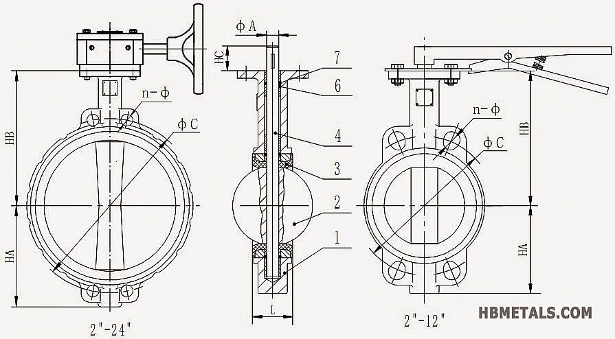
2. G.A drawing of cast iron wafer type butterfly valve.
3. Materials for cast iron wafer type butterfly valve.
|
ITEM NO.
|
DESCRIPTION
|
MATERIALS
|
|
1
|
Body
|
ASTM A126 Grey Iron, ASTM A536 Ductile Iron
|
|
2
|
Disc
|
Ductile Iron, Aluminum Bronze, SS304, SS316, Monel
|
|
3
|
Stem
|
SS416, SS304, SS316, Monel
|
|
4
|
Seat
|
Buna-N, EPDM, PTFE, Neoprene, Viton
|
|
5
|
O-Ring
|
Buna-N(Viton as optional)
|
|
6
|
Bushing
|
PTFE
|
4. Dimensions and data sheet.
|
SIZE
|
HA
|
HB
|
HC
|
L
|
Φ A
|
DIN PN10
|
DIN PN16
|
ASME B16.1
|
JIS 10K
|
|||||
|
DN
|
INCH
|
Φ C
|
n - Φ
|
Φ C
|
n - Φ
|
Φ C
|
n - Φ
|
Φ C
|
n - Φ
|
|||||
|
50
|
2"
|
66
|
130
|
30
|
43
|
12.7
|
125
|
4-18
|
125
|
4-18
|
129.5
|
4-19
|
120
|
4-19
|
|
65
|
2-1/2"
|
75
|
140
|
30
|
46
|
12.7
|
145
|
4-18
|
145
|
4-18
|
139.5
|
4-19
|
140
|
4-19
|
|
80
|
3"
|
95
|
150
|
30
|
46
|
12.7
|
160
|
4-18
|
160
|
8-18
|
152.5
|
4-19
|
150
|
8-19
|
|
100
|
4"
|
107
|
170
|
30
|
52
|
15.8
|
180
|
8-18
|
180
|
8-18
|
190.5
|
8-19
|
175
|
8-19
|
|
125
|
5"
|
122
|
185
|
30
|
56
|
19.1
|
210
|
8-18
|
210
|
8-18
|
216
|
8-22
|
210
|
8-23
|
|
150
|
6"
|
134
|
205
|
30
|
56
|
19.1
|
240
|
8-23
|
240
|
8-23
|
241.5
|
8-22
|
240
|
8-23
|
|
200
|
8"
|
168
|
235
|
36
|
60
|
22.2
|
295
|
8-23
|
295
|
12-23
|
298.5
|
8-22
|
290
|
12-23
|
|
250
|
10"
|
200
|
270
|
36
|
68
|
28.6
|
350
|
12-23
|
355
|
12-27
|
362
|
12-25
|
355
|
12-25
|
|
300
|
12"
|
237
|
305
|
36
|
78
|
31.8
|
400
|
12-23
|
410
|
12-27
|
432
|
12-25
|
400
|
16-25
|
|
350
|
14"
|
262
|
330
|
36
|
78
|
31.8
|
460
|
16-23
|
470
|
16-27
|
476
|
12-29
|
445
|
16-25
|
|
400
|
16"
|
300
|
360
|
51
|
102
|
33.3
|
515
|
16-27
|
525
|
16-30
|
539.5
|
16-29
|
510
|
16-27
|
|
450
|
18"
|
350
|
395
|
51
|
114
|
38.0
|
565
|
20-27
|
585
|
20-30
|
578
|
16-32
|
565
|
20-27
|
|
500
|
20"
|
375
|
440
|
64
|
127
|
41.2
|
620
|
20-27
|
650
|
20-33
|
635
|
20-32
|
620
|
20-27
|
|
600
|
24"
|
435
|
500
|
71
|
154
|
50.7
|
725
|
20-30
|
770
|
20-36
|
749.5
|
20-35
|
730
|
24-33
|
*DIN refers to flange bolting dimensions of European and German standards.
*JIS refers to flange bolting dimensions of JIS B2220.
*ASME B16.1 refers to ANSI/ASME flange bolting dimensions.
*All dimensions are in mm unless otherwise specified.
Views: 5100 Author:METALS INDUSTRIAL Date:2015/02/23


